In this case, a material test was conducted at our testing facility to establish the conveying rate and air usage. The operating principle of a conventional Roots type blower is quite simple. Web page addresses and e-mail addresses turn into links automatically. Correctly specifying the volumetric flow rate and pressure levels required to move the material will determine system reliability. RAM stands for Reliability, Availability, and Maintainability. Remember that the material needs to be conveyed in 4.1 min or less, so a 4-in., schedule 40 pipe will work for this application. Step #4 Chances are the Airlock is the Culprit. Step #5 conveying phase pneumatic systems dilute dense system primer figure So, 2,100 lb/cycle 635 lb/min = 3.30 min. Select the number of cycles per hour based on the convey distance. For non-free flowing materials with high angle of repose, special considerations need to be given to the receiver design and discharge valve. 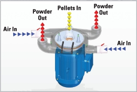 Step #2
Alternatively, vacuum receivers may use feeders or rotary valves to meter the material directly into the process thats continuous conveying. 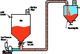 Dilute Phase: Product material is entrained in air stream in equal Material-to-Air ratio. A 3-in. line deliver? startxref
Learn about the latest advancements in the plastics industry from experts at Conair, Arburg, Davis-Standard & Milacron. The focus is on product-contact surfaces, which are typically all metallicplastics are not used for reasons of static control and contamination. Keep all conveying lines as straight as possible, minimizing any changes in elevation or direction? As a first step, it is important to know more about the powder that is being conveyed, specifically its bulk density. Registered in England and Wales. 0000008324 00000 n
Materials of construction are critical in the design and functionality of a vacuum-conveying system. Every 4.5 minutes the transporter needs to have completed a cycle to make the system rate note that the total cycle must include filling and conveying. ROOTS-FLO rotary positive displacement blowers are heavy-duty rotary units in a compact, sturdy design engineered for reliable pneumatic conveying of grain and similar products.
Dilute Phase: Product material is entrained in air stream in equal Material-to-Air ratio. A 3-in. line deliver? startxref
Learn about the latest advancements in the plastics industry from experts at Conair, Arburg, Davis-Standard & Milacron. The focus is on product-contact surfaces, which are typically all metallicplastics are not used for reasons of static control and contamination. Keep all conveying lines as straight as possible, minimizing any changes in elevation or direction? As a first step, it is important to know more about the powder that is being conveyed, specifically its bulk density. Registered in England and Wales. 0000008324 00000 n
Materials of construction are critical in the design and functionality of a vacuum-conveying system. Every 4.5 minutes the transporter needs to have completed a cycle to make the system rate note that the total cycle must include filling and conveying. ROOTS-FLO rotary positive displacement blowers are heavy-duty rotary units in a compact, sturdy design engineered for reliable pneumatic conveying of grain and similar products.
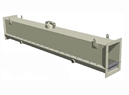
Scaling valves or positive pressure systems may also be a consideration for headroom requirements. 0000007141 00000 n Other considerations include defining whether the material is free-flowing, abrasive, or combustible; whether it absorbs moisture; and whether there potentially could be chemical compatibility issues with conveying hoses, gaskets, filters, or process equipment. If not, dont worry. The test was conducted on a 165-ft line, in a 3-in. Production and inventory are being scheduled and controlled to ensure these units will be available when you need them. Additionally, consider plant environmental conditions and temperature/humidity control. Like the rule in Step #10, the instantaneous air usage during conveying is directly proportional to the cross-sectional area of the conveying pipe being used. With the transfer rate established, select the proper line size that will deliver the material at a rate of at least 512 lb/min. For example, if a process requires conveying 2,000 lb/hr. He is a registered professional engineer working for over 35 years with rotating equipment and petrochemical processes. 0000012711 00000 n Determine the instantaneous conveying rate required during an individual cycle. The key to dense phase sizing--particularly with new materials--is to conduct material testing to help validate the system design. In dilute phase systems, the large pressure drop from source to receiver means that high pickup velocity is used to get the pellets moving, and air and material conveying speeds continue to accelerate all the way, often reaching extremely high speeds (>5,500 ft/min and higher) that can cause resin attrition and system erosion. Where do you begin and how do you proceed? 0000010102 00000 n Step #9 Blanton, Roger E., Get the Most Out of Your Rotary Lobe Blower, Chemical Engineering, vol. %PDF-1.5 All rights reserved. Changing the sheave sizes on belt driven blowers. Most of the time these guidelines are usually spot on, but what happens when a fundamental assumption turns out to not be accurate? YD1s|!{[pqR9Aq%b-8B|1wA. Step #12 Weve received your inquiry and will get in touch shortly. Typically, a standard 8-in. They are used extensively in dilute phase applications where the bulk material is conveyed through the pipeline in suspension, and the required pressure does not exceed 15 PSIG. When designing a vacuum conveying system, it is important to clearly define how the materials are received and introduced to the process. The important thing to remember is that sizing rules, like other rules, are made to be broken. Prior to performing the calculations, a brief overview of dense phase pneumatic conveying is helpful to understand. Here are 12 dos and donts for your consideration: For applications where materials and throughput may change from day to day like a custom mold shop that changes molds frequently or when plant production varies day to day a system design engineer will typically plan throughputs based on a worst case scenario.. Step #3 848 SCF/cycle x 13.3 cycles/hr = 11,278 cu ft /hr. For more information please contact Roger Blanton, P.E., Howden Roots, at email:roger.blanton@howden.com or visit www.howden.com. of product, but the batch process requires conveying 2,000 lb every 5 min. However, what happens after the resin enters the conveying line is very different. Higher bulk density materials require faster transport velocity. A typical Up-and-In system offers a vertical lift from the floor level, conveying up to a receiver over an extruder or loss-in-weight feeder. It relies on more powerful vacuum pumps with greater lifting power. 0000010942 00000 n Learn about the latest advancements in the plastics industry from experts at Conair, Arburg, Davis-Standard & Milacron. 2022 Gardner Business Media, Inc. Privacy Policy Todays sessions include presentations on Industry 4.0, smart resin conveying, trends in the plastics medical device market, and Conairs new common control platform. So, what are the best-practices for designing vacuum conveying systems? He has specialized for the last 25 years in technical product design, application, and sales; new product development and introduction; sales and distribution management; and international business development. Find out if the material is coming from a loss-in-weight feeder, volumetric feeder, mixer, reactor, extruder hopper or any other equipment used to move material. This is an especially important consideration when installing equipment into an existing plant. Typical conveying rates in dilute phase may go up to 25,000 lb./hr. For example a well sized dilute phase pressure system going 200 feet would probably run somewhere between 6-12 PSIG, have a terminal velocity of between 4,500 6,000 fpm and have a material/air ratio of somewhere between 8:1 to 12:1, the specifics varying depending on the product being conveyed. Step #6 What is the air velocity during conveying? Not all, but several Howden Roots blowers are bi-rotational so they can be used for vacuum or pressure service. By minimizing the system logistics in #4, this will be vital to maximizing your systems potential. A company specializing in the design requirements of pneumatic conveying systems is best consulted for evaluating these requirements and specifying the required air or gas flow rate for the system. The rules about line loading (material/air ratios) are totally rewritten if you are dealing with large particles. 0000052390 00000 n Meaning a known instantaneous transfer rate through a given internal diameter of conveying line at a given distance, will be the rate through any other size conveying line with the same material at the same distance resulting in a direct proportion of the cross sections of the pipes. %
This is a key factor in calculating the size of the vacuum receiver. However, dilute phase conveying works only at very high speeds, typically 5,000 feet per minute and greater. (2,3) Its important to note that Roots blowers do not create internal pressure or vacuum, they simply overcome system losses. https://www.powderbulksolids.com/sites/all/themes/penton_subtheme_powderbulksolids/images/logos/footer.png. The heart of the pneumatic conveying system (air mover, solids feeder, pipeline, and separator) is the air mover. For example, 20 ft. vertically plus 20 ft. horizontally and two 90-degree elbows equals at least 80 ft. of conveying distance. vs. 2,000 lb over a 60-min. Vacuum receiver refilling feeder as part of continuous process. The same holds true on the vacuum line every mitered bend has a greater pressure drop then a sweeping CLR elbow even for air-only calculations. endobj 60 min/hr 13.3 cycles/hr = 4.5 min/cycle. A 33.3 cu ft transporter is not a standard size. pneumatic air slide system conveying industry processing conveyor systems slides bulk equipment as300 section standard 2022 Magnum Systems Inc. All Rights Reserved. In this article, we will demonstrate how to size a standard dense phase transporter system. line, use air at a rate of 257 SCFM. The numbers above arent important in and of themselves. 0000008915 00000 n Inherent by their design, a PD blower has both mechanical and thermal limitations because the impellers are machined to close tolerances and the clearances are very small. <>stream Most things we convey are between 30 and 60 pounds a cubic foot. 0000004824 00000 n 0000006306 00000 n schedule 40 pipe at distance 165 ft will deliver the alumina powder at a conveying rate of 635 lb/min.
Blockage occurs where the dynamic air or gas pressure in the system is at its minimum value. Manually sizing a dense phase pneumatic conveying system is often considered a black art -- a type of tribal knowledge learned and passed down over time by a handful of manufacturers. Much of this wasted resin is captured in filters, which must be cleaned regularly, or else it can clog filters and rob vacuum pumps of airflow, reducing their capacity and causing them to overheat. This step references the testing results which indicated a conveying rate of 370 lb/min in a 3-in. Key system sizing steps outlined using alumina powders as the sample dry bulk material to perform calculations. <<10576DBEB030F14290A0D727C1D3AEC8>]>>
The system will be a standard batch blow, purge design (purge design refers to clearing the entire line and transporter with air before refilling the transporter) needing to convey the material over 20 ft vertical plus 145 ft horizontal. Both resin attrition and system erosion increase exponentially as material conveying velocity increases, so the best way to reduce both is to choose conveying methods and equipment that can convey adequate material throughputs at the lowest velocity. Minimize the use of 90 bends in conveying lines, either vertically or horizontally, because these increase system backpressure and consume some of the vacuum potential of your pump, which reduces its available capacity to lift and move material. As a general rule inpneumatic conveying, when sizing a system we look primarily at pressures, velocities and line loadings to determine best what the line size should be. 0000010278 00000 n In recent years, Conair has developed a slower-speed, dense-phase resin-conveying technology called Wave Conveying.